Table of Contents
What is the 7 Segment Counter Circuit?
7-segment display counter circuits are widely used in various digital applications. These circuits can count numbers from 00 to 99 and can be easily cascaded to count higher numbers. A 7-segment display is a type of electronic display device that can display decimal numerals, as well as some letters and symbols. It consists of seven segments that can be individually turned on or off to display different numbers.
There are various types of 7-segment display counter circuits available, ranging from simple circuits that use basic components like timer IC 555 and decade counter IC 4026 to more complex circuits that use microcontrollers and programmable logic devices. These circuits can be used in a wide range of applications, including digital clocks, stopwatches, timers, and scoreboards.
Building a 7-segment display counter circuit requires basic knowledge of electronics and circuit design. It involves selecting the right components, designing the circuit diagram, and assembling the circuit on a breadboard or PCB. There are many online tutorials and resources available that provide step-by-step instructions on how to build these circuits. With the right tools and knowledge, anyone can build a 7-segment display counter circuit for their digital projects.
Design of 7 Segment Counter Circuit
Designing a 7 segment counter circuit requires careful selection of components and a clear understanding of the circuit diagram. Here are the two sub-sections that will be discussed in this section:
Selection of Components
The components used in a 7 segment counter circuit must be carefully selected to ensure proper functionality. Here are some of the key components:
- Counter IC: A counter IC, such as CD4033, is used to count the input pulses and output the count value to the 7 segment display.
- 7 Segment Display: A 7 segment display is used to display the count value. There are two types of 7 segment displays: common anode and common cathode. The choice of display type depends on the counter IC used.
- Resistors: Resistors are used to limit the current flowing through the 7 segment display and prevent damage to the display.
- Capacitors: Capacitors are used to stabilize the power supply and prevent noise from affecting the circuit.
- Switches: Switches are used to start and stop the counting process and reset the count value.
Circuit Diagram
The circuit diagram for a 7 segment counter circuit is relatively simple. Here is a basic circuit diagram:
| Component | Description |
| CD4033 | Counter IC |
| 7 Segment Display | Display for count value |
| Resistors | Limit current through display |
| Capacitors | Stabilize power supply |
| Switches | Start, stop, and reset counting process |
The circuit diagram shows the connections between the components. The input pulses are fed into the counter IC, which counts the pulses and outputs the count value to the 7 segment display. The resistors limit the current through the display, and the capacitors stabilize the power supply. The switches are used to control the counting process.
Working of 7 Segment Counter Circuit
The 7 Segment Counter Circuit is an electronic device that counts and displays numerical digits. It uses a 7-segment display, which is also known as a seven-segment indicator and has seven LEDs. The circuit is quite easy and self-explanatory, and it can be used in conjunction with various circuits where a counter to display the progress adds some more attraction.
Clock Pulse Generation
The clock pulse generation is the first step in the operation of the 7 Segment Counter Circuit. The clock pulse is generated using a 555 timer IC, which is connected in astable mode. The frequency of the clock pulse can be adjusted using the potentiometer connected to the 555 timer IC. The clock pulse is then fed to the input of the decade counter IC, which counts the number of clock pulses.
Decade Counter Operation
The decade counter IC used in the 7 Segment Counter Circuit is the CD 4033. It is a 5-stage Johnson decade counter with 10 decoded outputs. Each output is connected to a segment of the 7-segment display. The counter counts the number of clock pulses and displays the count on the 7-segment display. The counter can count from 0 to 9, and then it resets to 0.
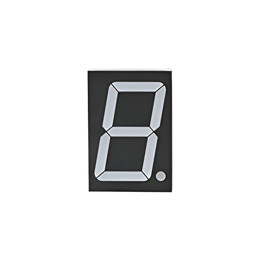
Displaying Count on 7 Segment Display
The 7-segment display used in the 7 Segment Counter Circuit consists of seven LED’s, one for each segment. Each LED has two terminals, an Anode and a Cathode. The Anodes of all the LEDs are connected together and are connected to the positive supply through a current-limiting resistor. The Cathodes of the LEDs are connected to the outputs of the decade counter IC. When a particular output of the decade counter IC goes high, the corresponding LED of the 7-segment display lights up, and the count is displayed.
Most Important Components to Note
The following components are essential to build a basic 7 Segment Counter Circuit:
- 7-segment display
- Counter IC (such as 74LS90 or 74LS93)
- Driver IC (such as 74LS47 or 74LS48)
- Resistors
- Capacitors
- Power supply (DC)
- Jumper wires
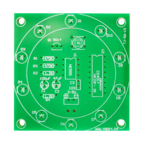
Circuit Schematic
The circuit diagram of a basic 7 Segment Counter Circuit is shown below:
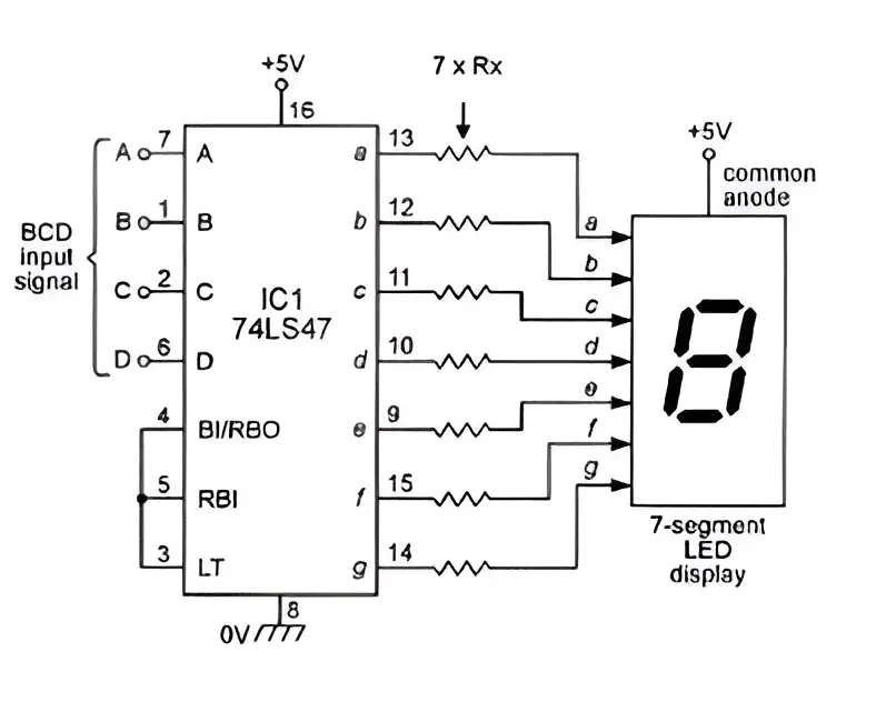
The circuit shows a simple 00 to 99 digital counter using a BCD Counter and two 7-segment display drivers. To count above 99, we would need to cascade more counter circuits together. A 4-digit BCD counter would count in decimal from 0000 to 9999 and then reset back to 0000.
The circuit uses a BCD (Binary Coded Decimal) counter to count from 00 to 99. The counter output is then fed to two 7-segment display drivers, which convert the BCD code into a format that can be displayed on the 7-segment display. The resistors and capacitors in the circuit are used to stabilize the power supply and prevent noise and interference.
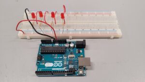
Instructions for Building 7 Segment Counter Circuit
Building a 7 segment counter circuit may seem daunting, but with the right instructions and tools, it can be a fun and rewarding project. The following steps will guide you through the process of building a 7 segment counter circuit using a NE555 timer and a decade counter IC 4026.
Step 1: Preparation
Before beginning the construction of the circuit, it is important to gather all the necessary components and tools. Here is a list of components needed:
- NE555 timer
- Decade counter IC 4026
- Common cathode type 7 segment LED display
- Resistors (220 ohm, 1k ohm, 10k ohm)
- Capacitors (0.1uF, 10uF)
- Transistor (BC547)
- Diode (1N4007)
- Breadboard
- Jumper wires
- Soldering iron and solder
Once all the components are gathered, it is important to double-check the circuit diagram to ensure that all the connections are correct.
Step 2: Soldering Components
The next step is to solder the components onto the breadboard according to the circuit diagram. It is important to solder the components in the correct order and orientation to avoid damaging the components or the circuit.
Begin by soldering the NE555 timer and the decade counter IC 4026 onto the breadboard. Then, connect the resistors, capacitors, transistor, and diode to their respective pins on the ICs. Finally, connect the common cathode type 7 segment LED display to the breadboard.
Step 3: Testing the Circuit
Once all the components are soldered onto the breadboard, it is important to test the circuit to ensure that it is functioning properly. Connect a power source to the circuit and verify that the LED display is showing the correct numbers as the counter counts up.
If the circuit is not functioning properly, double-check the connections and component values to ensure that they are correct. It may also be helpful to use a multimeter to test the voltage at various points in the circuit to identify any potential issues.
With these instructions, building a 7 segment counter circuit should be a manageable and enjoyable project. With careful attention to detail and testing, the end result should be a functional and rewarding circuit.
Conclusion and Final Thoughts
7-segment counter circuits are an essential component of digital electronics. They are widely used in a variety of applications, including calculators, digital clocks, and scoreboards. 7-segment displays are simple and easy to use, making them a popular choice for displaying numerical data. The circuitry is relatively straightforward, and the displays themselves are inexpensive and widely available.
There are many different types of 7-segment counter circuits, each with its own unique features and advantages. Some circuits are designed to count up or down, while others can count in both directions. Some circuits can display decimal points, while others cannot. Additionally, some circuits are designed to work with specific types of displays, such as common anode or common cathode displays.
Despite the many variations in 7-segment counter circuits, they all share a common goal: to accurately display numerical data. Whether you are building a simple digital clock or a complex electronic device, a 7-segment counter circuit is an essential component that you cannot afford to overlook. By understanding the basics of how these circuits work and the different types available, you can choose the right circuit for your needs and build a device that will perform reliably and accurately for years to come.
If you are into more electronics we build, then we suggest you check out our projects and stories on our blog.