
Table of Contents
Hey guys and welcome back to what is the post I really wanted to share you all! Back to work and in the Workspace I was on! Finally, I get more time and picture to start sharing and blogging on my new passions. Welcome to the Electronics portion of the new ride. Join me in my new journey. Let’s begin.
If you didn’t see Part 1 of my Workplace – well, previously on Part 1, here’s a recap. I will be showing how to solder and repair items for you once I fully mastered repairs and the deeper understanding. My deeper understanding will soon be transferred here as I learn to solder and repair well. They will act as tutorials on Fluids Web.
What is a Winky Blink?
A Winky Blink is considered to be a very simple electronic circuit that can be used to create an LED (light emitting diode) blink or flash (flashing requires clean soldering and that’s what I tired to do.) The circuit utilizes a resistor, a capacitor, and a transistor to power up the LED.
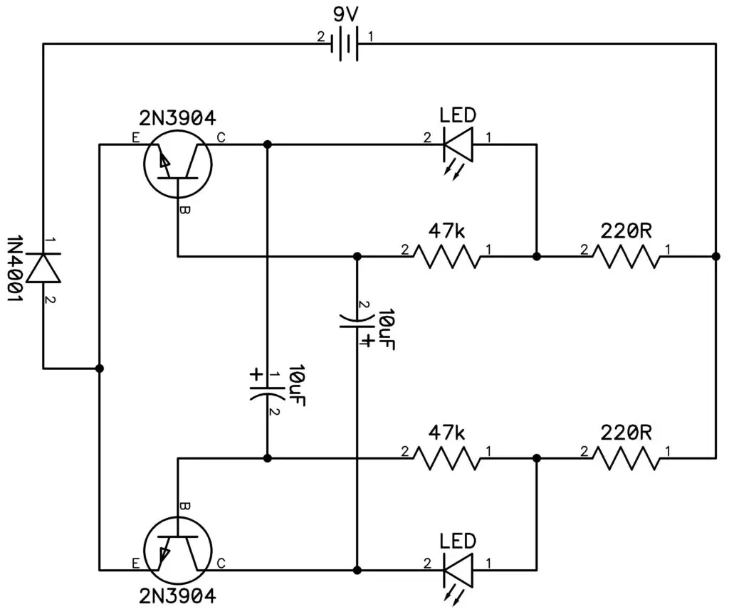
The goal is to get the power through the board and let the capacitor run through the LED. That is what keeps it from blinking. I had challenges of my own and the Capacitors are probably the most hardest part. Schematic down below as follows.
How did I progressed on my own Winky Blink board?
Here you see before you, this is a circuit board I screwed up on only to put to much solder on the circuit, the circuit also got dirty. Don’t worry, I did managed to fix it and got a new circuit to potentially light up with 2 LEDs.
I have finished up one of my favorite projects which is the Winky Blinky 2.0. Sorry for making it too easy for you guys, you won’t see any small projects like this on Robot2Guides. I promise you. The Winky Blinky 1.0. version would come with two pop-out images, from there you can attach a face for example – a robot and have it’s eyes blink! But for us, it’s the Winky Blink 2.0. I will be sharing for this blog.

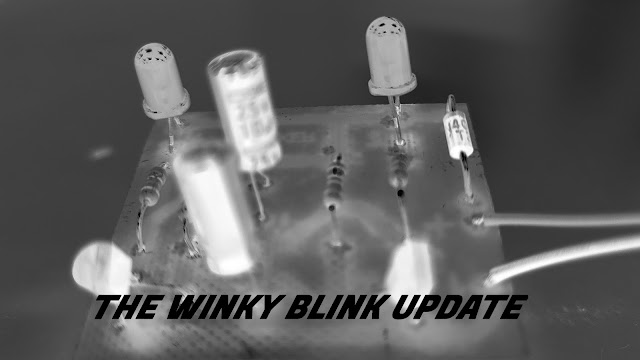
So here’s the result of the Winky Blinky 2.0. It turned down right messy when the soldering got dirty and many of the connections refuses to power up. It was a problem in my end, just pushing the soldering pen for a long time causes burns on the board and leaves a mess I always forget.
It reminds me to always be careful at all times, I suppose! The only rare occurrence is when the light stays on in it’s darkest form – meaning it barely lights up. It needs a new resistor so it had to have 210 ohms when testing on a breadboard.
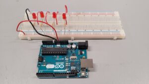
The breadboard’s connection to the LEDs seem to work just fine and the lights blink, but with higher resistance, the LEDs light up way more. This proved to be the case when I swapped out a 150 and 200 ohms resistor. Finally went to the real board and had to replace the 2 resistors that made the low light to the LEDs.
Soldered them up and have yet to test it. Do you think it will work? Stay tuned for Me in the Garage – Part 3 (The Ardunio Part 1) to find out and see the recap later on!
Andrew Drive’s reaction: “Simple but yet great to jot down. If you can follow a schematic and parts then you’d be a breadboard and circuit professional – practice makes perfect.”
How I did it myself
I explained that it turned down right messy when the soldering got dirty and many of the connections refuses to power up. It was simply something I made on my end, pushing the soldering pen for a long time causes burns and a mess on the board I wasn’t aware of. I just needed to have a grip and be more precise when it comes to soldering. After a few attempts to get all of the connections in, it barely lights up.
One mistake I did was I didn’t solder the capacitors properly. Looking at the back connections of the board – it had a hole when the solder liquid went through. It didn’t fill it in all the way.
I did came across time to repair it after my short 10 minute break. After soldering the hole, we tried it again with power on the main board and it still barely lighted up. It simply needed a new resistor so I upped it up to 210 ohms when testing on a breadboard.
Supposing that we went back to the breadboard, if I knew what kind of connection it takes, I said to myself, how much resistance can the voltage take? From the science, resistance can increase and voltage can drop, simply put. Too much to talk. It needs math and I don’t have my notes right now, I will blog my notes later on.
At the end of practicing deeply, knowing that the resistance for example, when I plug in a 210 ohm resistor, It shines the light very brightly. Why? I had to experiment on the breadboard. Now we needed to follow a schematic. Knowing that some of these numbers makes up a total of 210 ohms, down below.
Working through the Power Schematic
After following the schematic, R3 and R4 had it’s label of 100 ohms and 1,000 ohms. 10k and 100k ohms for R1 and R2 respectively.
So we rerouted the resistors on the breadboard, following a schematic is kinda tricky for me when I use a breadboard, it takes time to be honest. Plugging it in causes a good amount of light and it blinks – L1 blinks first – L2 blinks second. I also tried Blue and Red LEDs as well.
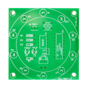
It was time to replace the Winky Blink board since the board was damaged and the drill pressing was seemingly crooked.
We started over on a new board. I didn’t liked the Yellow color of the board so I decided to spray paint it light green. (I was unsure if spray painting affects the board’s performance but I did it anyways.) Then, I went to drill the holes in for the components to go through.
Conclusion and Final Thoughts.
After creating the holes, I re-soldered all of the connections together without leaving a sufficient mess on the board, and at last, it lights up like a Winky Blink! My photos were corrupted at the time of filming and my Winky Blink was stored so I wasn’t able to share the full results on video.
Anyways, at the end, this project is simple and I recommend this for beginners and see what kind of experience you can develop with the Winky Blink.
That’s will do it for that Project. See you next time for Me in the Garage, The Water Piano. Sneak Peek will be coming soon. Feel free to leave a comment down below for any other ideas you want share or want me to document. We’ll meet again in the next post.


[…] Hello. I am back with another Me in the Garage Series. I hope you enjoy this article as much as the other one because I spent more time writing a longer episode for you today. Stay tuned for more episodes coming as the days go by. Today, we finally move to the Water Piano circuit after a intense run but very easy to set out on the Winky Blink project. […]