Table of Contents
Welcome back to more of the classic “Me in the Garage” Series editions here on Fluid’s Web! My previous Episode – didn’t get a good web ranking the last time I had to write it all down, despite all of the effort made towards the Water Piano so I will try to sum up all of the previous episode while having the next part in motion.
Feel free to comment down ideas or strategies for the next part and feedback as well. Those will help. Thanks for the support! Let’s start with today’s main focus of the Post. The Conclusion of the Water Piano.
So what happened last time?
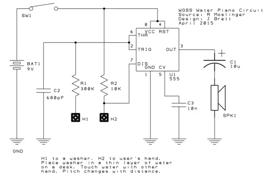
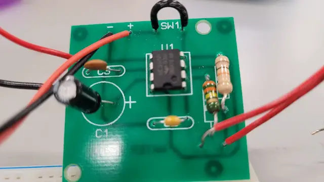
Last time, we stopped at whether or not the Water Piano did work or not. We went through pretty much the entire process of mapping the board’s components which introduced the 555 Timer and a speaker for the output audio – and contained previously mentioned components just like on the Water Piano which was 3 capacitors: (10uF, 680 pF and 10nF), 2 Resistors: (300k, and 10k), a Switch and a battery clip.
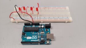
When we tested them on to a Breadboard, things were bumpy and sometimes it didn’t work, however, the breadboard made it easy for us to troubleshoot our mistakes. Once after now and then, we began the process of putting together on the real board and that had problems to but what we don’t know is whether it worked or not the third time around. So here is the quick and brief story for you all now, the conclusion of the water piano.
Circuit Breakdown
So let’s get into the real breakdown of the Water Piano. The Water Piano allowed us to introduce a new circuit, the 555 Timer circuit, which controls the frequency of the Water Piano’s standard pitch and controls when the line of water makes contact with the user’s finger and the circuit..
Then from here: pieces from the other circuit we already know, This circuit uses 3 capacitors: (10uF, 680 pF and 10nF), 2 Resistors: (300k, and 10k), a speaker for the output audio and a Switch….. (my equipment and inventory is so low that we needed to find an alternative to a switch.) Down below is a schematic you can take a look at the objective we have to complete.
What is a 555 Timer?
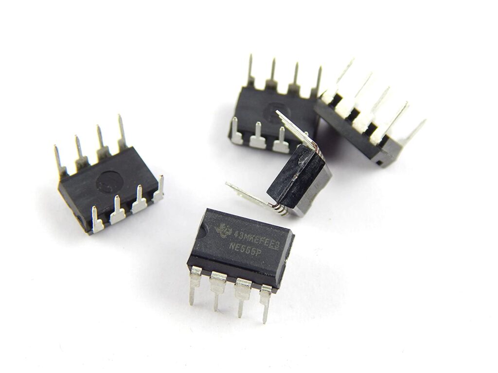
A 555 Timer is the most important part of the Water Piano and acts as a Brain to the circuit. In detail, The 555 timer consists of two comparators, a flip-flop, a voltage divider, and an output stage.
The voltage divider is used to set the trigger and threshold voltages for the comparators, while the flip-flop is used to store the output state of the timer. The output stage is used to drive external loads such as LEDs, motors, or relays. In this case, the Timer is used to create the piano’s tunes.
We will link a 555 Timer that will be in use for this project. You can also buy it for yourself on Amazon.
Let’s get into the story!
Alright, When we originally tested it on a Breadboard, sometimes, it didn’t work or play the test sound, it can only start up when the battery is hooked up and that’s all it can do, another major problem was that the capacitors was wrong.
The 10uF was not attached well. When trying to the real green colored board, it struggled to produce a sound as well. One of the reasons was that the Soldering didn’t make a clear connection, there were small holes that didn’t allow the power to go through, neither for it to work so we had to fix those issues.
Same goes for the second time. Did the third round go as planned? It didn’t work…… what happened was the speaker soldering was so terrible, it’s heavy weight made it fell off. That also broke part of the speaker as well. The storage was out of speakers by the time I was able to get one and it broke the way that I didn’t want to see, happen at all.
So I didn’t get a new speaker until two – three weeks, which is exactly the time when this post had to be put on hold! We needed to get a new speaker urgently so the wait just had to begin.
Once touching down on the speaker, I said to myself, I hope that this is going to make it and hopefully it works! So until then, I focused on different aspects of my life and the blog as well until I can get a new replacement.
My friends were waiting for me at work so I didn’t have lots of time popping by at the garage most of the time until the very next week (and another….).
When the speakers arrived…
It’s January 31st and the new speakers finally arrived. I also had to check the garage every once a while to see if I got any speakers as well, even when work is finished. We’ve placed 2 speakers so I can use the other for the next upcoming project on the Roulette Wheel (which I hope I can manage to do at some point.)
So we got the speakers, and finally, I can add the red and black wires over to the speakers – connecting to the circuit and solder them together. The wires had to go into the metal holes and the end wires had to be bent so slightly that the connections going through can power and be soldered correctly.
Once we got those in, we tested it with the Washers, and it plays the sound really well! Already taking note that the other components were already soldered correctly……. it worked like a Piano masterpiece.
We can finally snip out the metal wires sticking out and it’s time to go! It’s finished! I am so happy about the ending outcome of the circuit and it sure was fun and challenging to build this project.
Now we have finished the Water Piano! Great for showing off the awesome sounds of the circuit!
Something I learned was that it takes time to build on these projects, it doesn’t have to be rushed to get the perfect masterpiece but it does take time and the effort put in to see the successful result.
That concludes the Water Piano. Truly some kind of a project – a challenging version I sure recommend for the people out there who are into electronics. My round here wasn’t too amazing. I had to wait for days to get a new speakers which was frustrating so that was the challenge .
I overcame and I am happy about the outcome after resolving the problem. Thank you to all who have read Part 1 and 2 on the Water Piano. This project was a challenge but it a recommend for some experts who already got through the Winky Blink, they should master Water Piano next.
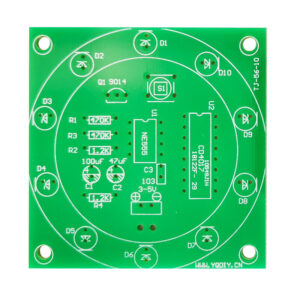
Sneak Peek of the Roulette Wheel.
Here is an upcoming Sneak Peek in words about the Roulette Wheel! The Roulette Wheel is composed of several LEDs and specific components to make the lights spin until they stop! The circuit is also comprised of the previous two main projects – the Winky Blinky v2.0. (of course) and the Water Piano – which specifically used the Speakers once again, to make a “Wheel Styled” sound when the lights activate.
Reprising with a few capacitors and resistors makes these projects a much harder one. We also got a Surprise Fixing episode coming up, which comprises of a special circuit which I will try to fix….. What would that be? Please stay tuned for that as well!
That will do it for this Project. See you next time in Me in the Garage, Part 6. The Special Edition Fixing Surprise & The Start of the Roulette Wheel. Those will be coming soon. Feel free to leave a comment down below for any feedback or other ideas you want to share if you want me to document in a later post. We’ll meet again in a brand new and different article then on Fluids Web.